Grain structure in the metal sheet is critical for avoiding cracks in sheet metal parts with lugs or tabs that are cut on.
Relief cut sheet metal.
We would like to show you a description here but the site won t allow us.
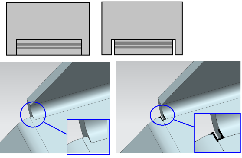
To eliminate this a bend relief is added so the edge of the sheet metal is perpendicular to the bend.
The width of the relief should be the material thickness or greater.
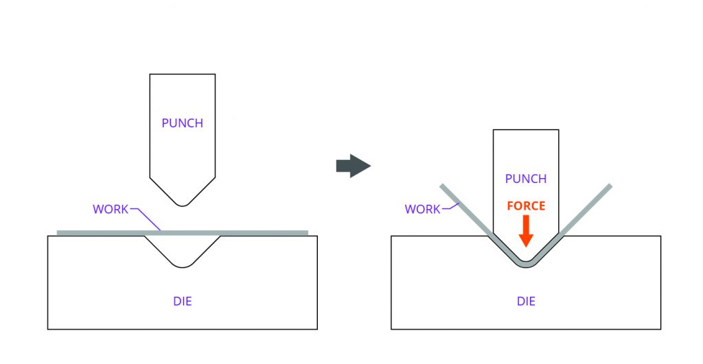
Sheet metal fabrication is the process of forming parts from a metal sheet by punching cutting stamping and bending.
Bend relief synchronous sheet metal is pretty cool even cooler than just normal synchronous modeling if you ll excuse that word.
One benefit of a bend relief is that it makes the part easier to produce.
Bend 1 shows a a tear relief.
Figure c shows a bend relief cut into the part again the depth of the relief should be greater than the radius of the bend.
For example if you make a partial flange as above using all the defaults the software makes relief cuts at the end of the bends as shown to the right.
The width of the relief should be a material thickness or greater preferably a material thickness 1 64.
Under corners click collect all corners to list all corners in the sheet metal body.
If you select rectangular or obround specify the relief ratio.
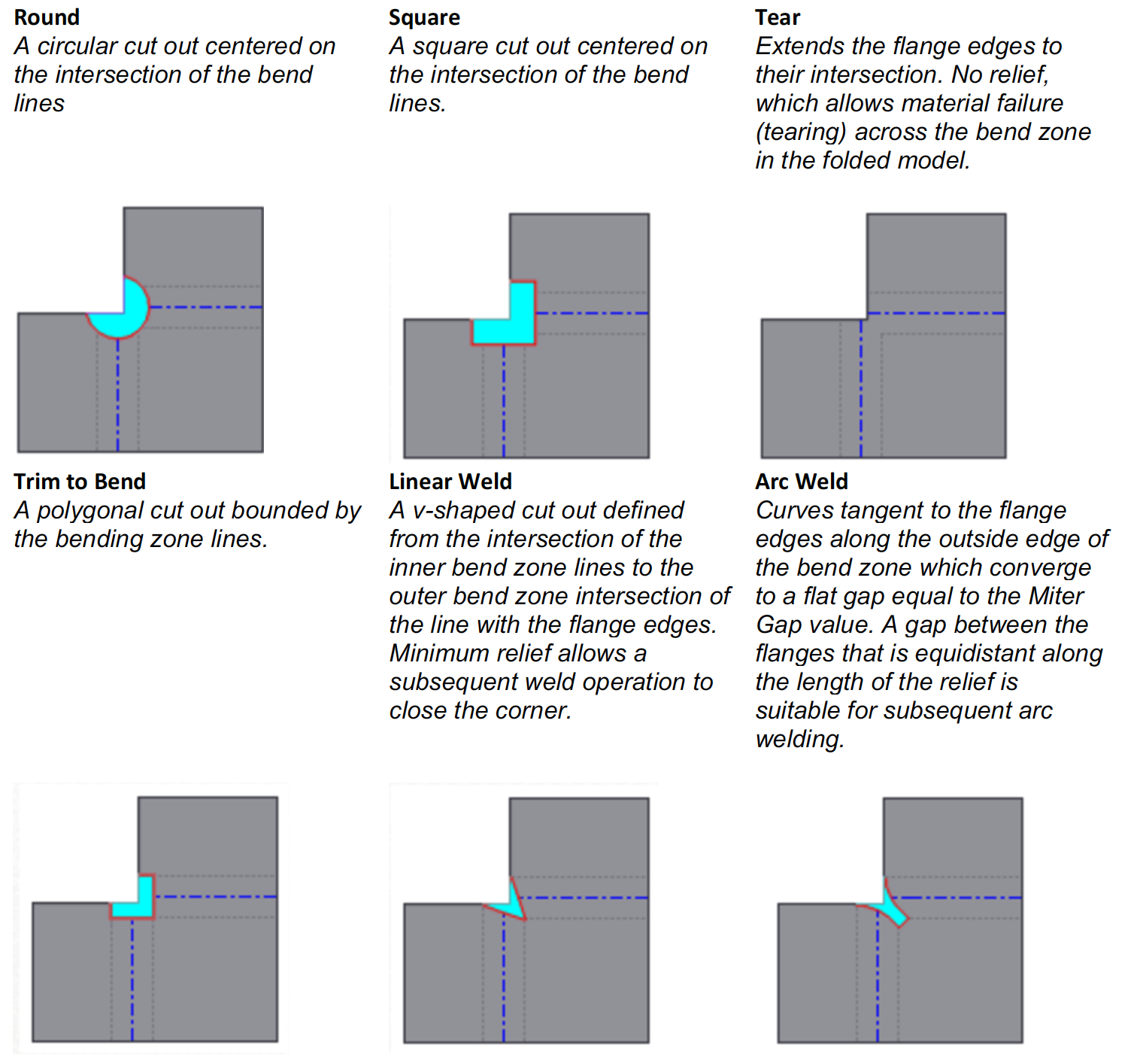
To change the type of relief cut for all bends.
Bend 2 shows a rectangular relief cut into the part the depth of the relief should be greater than the radius of the bend.
Relief cuts help parts avoid overhangs and tearing at bends.
You can add a corner relief to a single sheet metal body.
Click corner relief sheet metal toolbar or insert sheet metal corner relief.
In general a minimum bend relief is equal to the material thickness plus the inside bend radius.
In the propertymanager under auto relief change the type of relief cut.
Sheet metal parts may have sharp corners but designing a fillet of the material s thickness will make parts more cost effective.
Bend relief and collars near pierced areas strengthen sheet metal parts.
Right click the sheet metal feature in the featuremanager design tree and select edit feature.